Environmental requirements
Due to the complex working environment of mechanical equipment, the selection of chain drive must be based on the working conditions to select the appropriate composition of materials and their hardness. The details are as follows:
The wear resistance
S when some equipment operation, can't avoid to be exposed to sand, soil, straw hin particles and other sundry, the particles will fall into the sleeve and the gaps between the roller and roller chain and sprocket meshing positions, like grinding sand grinding grain, can produce scratch on the surface of the contact, thus speeding up the chain and sprocket wheel wear, shorten the service life. Preventive measures include:
1) Add a sealing protective cover to the transmission mechanism of the chain to prevent these sundries from entering the chain drive system.
2) Let the chain run slowly, and reduce the number of chain and sprocket engagement.
3) Use larger chain or multiple rows of chain to reduce the pressure (refers to the pressure between sleeve and roller, pin and sleeve).
■ If for some reason these three methods are not feasible, you can use the following measures:
1) Use bearing steel or chrome-molybdenum steel and other materials to manufacture parts and components, and improve their wear resistance through heat treatment and hardening measures.
2) Hardened steel can be used as a manufacturing material when the chain plate is subjected to considerable wear.
3) The sleeve has the highest wear rate, so its thickness can be imposed to reduce the pressure on the bearing surface, and wear-resistant steel is used as the manufacturing material.
Fatigue resistance
Due to the special conditions of mechanical equipment operation environment, the fatigue resistance of the chain has high requirements, so it can be considered to use heavy chain, or multi-row chain to improve.
The oxidation resistance
For the chain directly in contact with water (such as cleaning machine chain, rice chain, etc.), oxidation rust will occur and cause the gradual wear of the chain, so the chain used in this environment needs to undergo certain anti-rust treatment measures, or the use of stainless steel or other chain with good water resistance. In addition, it is necessary to increase the clearance of the hinge part to prevent the deposition of rust.
Calculation and Selection
Chain standard operation
■ Standard operation conditions of the chain are as follows:
A) single row chain without half-mesh link
B) The number of teeth of the driving sprocket is 35 teeth
C) Two sprocket drive mounted on a horizontal parallel shaft
D) The working environment temperature shall be between -5℃ and 70℃
E) Transmission reduction ratio can reach 3:1
F) The expected service life of the chain is 15,000h
G) The chain length is 120 chain joints. If the chain length is less than this length, the service life will be reduced by this proportion
H) Stable operation, no overload, impact or frequent start
I) See item 2 of "Guide for Installation, Inspection and Maintenance of Chain Drives" for cleaning and proper lubrication
J) The sprocket is correctly aligned and the chain is adjusted correctly. See the first item of "Guide for Installation, Spot Inspection and Maintenance of Chain Transmission"
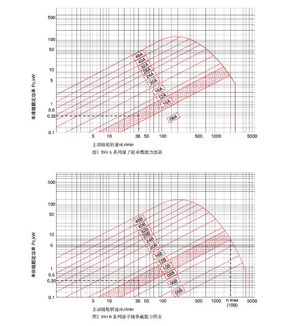
■ Figs. 1 and 2 are the chain bearing capacity charts established under the above conditions, showing the curves of the drive sprocket speed N1 and the modified power Pc corresponding to the chains of various specifications.
1) The rated power of double-row chain can be calculated by Pc*1.75 of single-row chain.
2) The rated power of three-row chain can be calculated by Pc*2.5 of single-row chain.
3) Pc calculation formula is as follows:
Pc = Pi x F1x F2
(Input power Pi refers to the power to be transmitted by the drive sprocket. If input torque is known, input power Pi=M x N1/9550)
Other operating conditions
■ Working condition coefficient F1
The working condition coefficient F1 is the coefficient considering the degree of power overload, which is related to the running conditions of chain drive, especially the active and driven machinery and characteristics. The coefficient F1 value can be directly checked by Table 1, or selected by analogy with Table 2 and Table 3.
Table 1 Operating condition coefficient
Driven mechanical properties
(See Table 3) |
Active mechanical properties (see Table 2) |
| Smooth running |
A slight shock |
Medium impact |
| Smooth running |
1.0 |
1.1 |
1.3 |
| Medium impact |
1.4 |
1.5 |
1.7 |
| Severe impact |
1.8 |
1.9 |
2.1 |
Table 2 Definition of active mechanical characteristics
| Smooth running |
Internal combustion engines, electric motors, steam turbines and gas turbines with hydraulic couplings. |
| Medium impact |
Six cylinders (including) or more internal combustion engines with mechanical couplings, frequently started motors (starting more than twice a day). |
| Severe impact |
An internal combustion engine up to six cylinders with mechanical couplings. |
Table 3 Definition of driven mechanical properties
| Smooth running |
Centrifugal pumps and compressors, PRINTING machinery, uniform feeding belt conveyor, paper press, escalator, liquid mixer and mixer, rotary drying furnace, fan. |
| Medium impact |
Pumps and compressors with more than three cylinders (including), concrete mixers, conveyors with variable loads, solid mixers and mixers. |
| Severe impact |
Coal planers, electric shovels, rolling mills, ball mills, rubber processing machines, presses, cutting machines, single or double cylinder pumps and compressors, oil RIGS. |
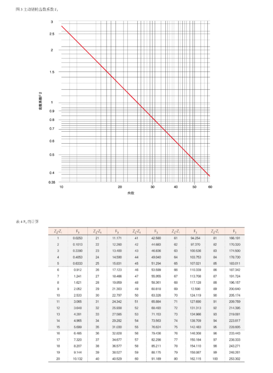
■ Number of teeth coefficient F1
The tooth number coefficient F2 is the coefficient considering the influence of the number of teeth of the active sprocket, and its value is looked up from FIG. 3.
The chain to choose
■ Select the single row chain with the smallest pitch from the load capacity diagram (see Figs. 1 and 2) according to the required power delivery and small sprocket speed.
■ In the requirements for compact transmission arrangement, you can consider the choice of a smaller pitch of the chain, so that the sprocket diameter will be reduced.
The chain length
According to the known chain pitch (P) and the primary center distance (C2), the following formula can be used to calculate the chain length of the two sprocket drive (Ln). The calculated number of chain length segments (Ln) should be rounded into an integer (L). If the number of chain length segments is selected to be even, the use of hemimesh segment chains can be avoided.
■ When the number of teeth of two sprockets is equal (Z=Z1=Z2) : Ln= 2xC2 / P + Z
■ When the number of teeth of the two sprockets is not equal: Ln= 2xC2 / P + (Z1+Z2) / 2 + F3xP/C2, where: F3=[(Z2-Z1) / 2]2, the calculated value of F3 is shown in Table 4.
The chain speed
The linear speed of the chain can be calculated as follows: V=N1xZ1xP/60000
Maximum sprocket center distance
After determining the number of chain joints (L) according to the above formula,
Calculate the maximum center distance between two sprockets (C1) according to the following formula
■ When the teeth of two sprockets are equal (Z=Z1=Z2),
C1 is equal to Px (L-z) / 2
■ When the number of teeth of two sprockets is not equal,
C1 = F4xPx [2 - (Z1 and Z2) l]
(The calculated value of F4 is shown in the left table)
L -Z1
Z2-Z1 |
F4 |
L -Z1
Z2-Z1 |
F4 |
L -Z1
Z2-Z1 |
F4 |
| 13 |
0.249 91 |
2.00 |
0.244 21 |
1.33 |
0.229 68 |
| 12 |
0.249 90 |
1.95 |
0.243 80 |
1.32 |
0.229 12 |
| 11 |
0.249 88 |
1.90 |
0.243 33 |
1.31 |
0.228 54 |
| 10 |
0.249 86 |
1.85 |
0.242 81 |
1.30 |
0.227 93 |
| 9 |
0.249 83 |
1.80 |
0.242 22 |
1.29 |
0.227 29 |
| 8 |
0.249 78 |
1.75 |
0.241 56 |
1.28 |
0.226 62 |
| 7 |
0.249 70 |
1.70 |
0.240 81 |
1.27 |
0.225 93 |
| 6 |
0.249 58 |
1.68 |
0.240 48 |
1.26 |
0.225 20 |
| 5 |
0.249 37 |
1.66 |
0.240 13 |
1.25 |
0.224 43 |
| 4.8 |
0.249 31 |
1.64 |
0.239 77 |
1.24 |
0.223 61 |
| 4.6 |
0.249 25 |
1.62 |
0.239 38 |
1.23 |
0.222 75 |
| 4.4 |
0.249 17 |
1.60 |
0.238 97 |
1.22 |
0.221 85 |
| 4.2 |
0.249 07 |
1.58 |
0.238 54 |
1.21 |
0.220 90 |
| 4.0 |
0.248 96 |
1.56 |
0.238 07 |
1.20 |
0.219 90 |
| 3.8 |
0.248 83 |
1.54 |
0.237 58 |
1.19 |
0.218 84 |
| 3.6 |
0.248 68 |
1.52 |
0.237 05 |
1.18 |
0.217 71 |
| 3.4 |
0.248 49 |
1.50 |
0.236 48 |
1.17 |
0.216 52 |
| 3.2 |
0.248 25 |
1.48 |
0.235 88 |
1.16 |
0.215 26 |
| 3.0 |
0.247 95 |
1.46 |
0.235 24 |
1.15 |
0.213 90 |
| 2.9 |
0.247 78 |
1.44 |
0.234 55 |
1.14 |
0.212 45 |
| 2.8 |
0.247 58 |
1.42 |
0.233 81 |
1.13 |
0.210 90 |
| 2.7 |
0.247 35 |
1.40 |
0.233 01 |
1.12 |
0.209 23 |
| 2.6 |
0.247 08 |
1.39 |
0.232 59 |
1.11 |
0.207 44 |
| 2.5 |
0.246 78 |
1.38 |
0.232 15 |
1.10 |
0.205 49 |
| 2.4 |
0.246 43 |
1.37 |
0.231 70 |
1.09 |
0.203 36 |
| 2.3 |
0.246 02 |
1.36 |
0.231 23 |
1.08 |
0.201 04 |
| 2.2 |
0.245 52 |
1.35 |
0.230 73 |
1.07 |
0.198 48 |
| 2.1 |
0.244 93 |
1.34 |
0.230 22 |
1.06 |
0.195 64 |